
Why Truck Wheel Fasteners Loosen -- And Why Re-Torque After Service Is Non-Negotiable
Why Truck Wheel Fasteners Loosen -- And Why Re-Torque After Service Is Non-Negotiable
Every year, the Commercial Vehicle Safety Alliance (CVSA) conducts its International Roadcheck -- a 72-hour enforcement blitz across North America in which inspectors check tens of thousands of commercial motor vehicles against federal out-of-service criteria. Wheel end violations, including tires, wheels, and fastener conditions, consistently account for approximately 23 percent of all vehicle out-of-service violations found during these inspections. That means nearly one in four trucks pulled out of service has a problem at the wheel end that an inspector caught -- and that drivers and maintenance personnel did not.
The inspection record reflects a broader pattern. The National Transportation Safety Board has estimated that 750 to 1,050 tractor-trailers experience wheel separations each year in the United States, a figure widely regarded as conservative given underreporting of non-accident events (NTSB/SIR-92/04, 1992). Wheel separation is not a random mechanical failure. It is the predictable result of well-understood physical mechanisms that degrade fastener preload progressively, through heat cycling, vibration, and surface bedding-in. In many cases, the degradation is detectable well before catastrophic separation -- if the right tools are in place to detect it.
This article examines the four primary mechanisms by which wheel fastener clamp load degrades, presents laboratory data quantifying the thermal effect on a real-world wheel-off event, and discusses how visual indicator systems like Torque-Tight lug nut indicators integrate into a layered wheel safety protocol to catch loosening before it becomes a separation.

1. Fastener Preload Theory: Torque Is Not Clamp Load
The purpose of tightening a lug nut is to generate clamping force, also called preload, between the wheel and the hub mounting face. Preload is what prevents relative motion between mating surfaces. Without sufficient preload, fretting, fatigue, and ultimately fastener rotation can occur.
The relationship between applied torque (T) and generated clamp load (F) is expressed by the nut factor equation:
T = K × d × F
Where T is applied torque (N·m), K is the dimensionless nut factor (typically 0.15 to 0.20 for lubricated steel fasteners), d is the nominal bolt diameter (m), and F is the resulting clamp force (N).
The critical implication of this equation is that K is not a fixed constant. It is a composite term that captures all frictional losses in the system: under-head bearing friction, thread friction, and surface condition effects. In practice, as much as 40 to 50 percent of applied torque is consumed by thread friction and another 30 to 40 percent by under-head friction, leaving only 10 to 20 percent of the applied torque to generate actual clamp load (Eccles, Sherrington & Arnell, 2010, Proc. IMechE Vol. 224 Part C).
This means that two fasteners torqued to the same specification with different surface conditions -- one dry, one lightly contaminated with corrosion inhibitor -- can exhibit clamp load variations exceeding 25 percent at identical torque values. Torque is a process control tool, not a direct measurement of joint integrity. This distinction is foundational to understanding why torque wrench verification alone is an incomplete maintenance strategy, and why a complementary continuous monitoring method matters.
2. Thermal Effects: Differential Expansion Between Aluminum Wheels and Steel Hardware
Commercial vehicle wheels are increasingly specified in aluminum alloy, particularly in transit bus and long-haul fleets where weight reduction is a priority. Aluminum and steel have substantially different coefficients of thermal expansion (CTE): aluminum alloy wheel material expands at approximately 21 to 23 μm/m·°C, while steel studs and cast iron or steel hubs expand at approximately 11 to 12 μm/m·°C (Testlabs International Ltd., File No. 06C-TL1760, 2006).
As the aluminum wheel heats, it expands radially and axially at roughly twice the rate of the steel stud. The stud elongation and the wheel bore expansion occur at different rates, creating a transient reduction in clamp force across the joint interface. Upon cooling, neither surface returns precisely to its pre-heat geometry. Repeated thermal cycling progressively works the mating surfaces, and if the initial preload was marginal, even modest thermal events can drive clamp force below the threshold required to prevent micro-slip.
Controlled laboratory testing commissioned by the Yanke Group of Companies following a real wheel-off event on a Great Dane trailer (Kapuskasing, ON, March 2, 2006) produced data that quantifies this effect with precision. The investigation, conducted by Testlabs International Ltd. (Winnipeg, MB, File No. 06C-TL1760, Dr. Wayne W. Tennesey, P.Eng., June 8, 2006), tested a complete new wheel assembly -- two rims, one brake drum, one Conmet aluminum hub (part #150767), and ten Euclid flanged cap nuts -- using two temperature protocols designed to replicate the conditions of the incident.
In Test #2, the assembly was torqued to the specified 500 ft-lbs at -35°C, then allowed to warm to approximately 19°C (replicating cold-weather installation followed by operation in warmer conditions with brake heat). The torque audit at 19°C found that fastener torque had decreased to a range of 250 to 340 ft-lbs across all ten positions -- an average decrease of 211 ft-lbs, or 42 percent of the original applied torque (Testlabs International, 06C-TL1760). The report concluded that the probable cause of the wheel-off was inadvertent cold-temperature installation followed by brake-heat-induced warming, which drove this substantial reduction in applied nut torque.
A 42 percent torque reduction is not a marginal effect. In the context of a 500 ft-lb specification, it means the effective fastener state after the thermal event was roughly equivalent to having torqued the nuts to 289 ft-lbs at installation -- well below specification, and in a range where the Junker vibration mechanism (described in the next section) can drive progressive rotation to failure.
For transit agency maintenance operations where vehicles cycle through high-brake-use urban routes immediately after service, and for any fleet that services vehicles in winter conditions, the thermal mechanism is a primary risk factor that must be addressed in maintenance protocol design.
3. Vibration-Induced Loosening: The Junker Mechanism
The most mechanistically complete explanation of vibration-induced fastener loosening was published by Gerhard Junker in 1969 (SAE Technical Paper 690055), and the model he described remains the authoritative reference in fastener engineering literature.
Junker demonstrated that transverse vibration -- loading applied perpendicular to the bolt axis -- is far more destructive to preload than axial vibration. Under transverse loading, the relative motion between the bolt shank and clamped material causes micro-slip at both the thread engagement surface and the under-head bearing surface. Each micro-slip event produces a small, irreversible rotation of the nut relative to the bolt. The rotation is irreversible because the friction forces that resist slip are directionally asymmetric: the nut rotates a small increment in the loosening direction with each vibration cycle and cannot recover that rotation elastically.
The key parameters governing the rate of Junker loosening are the amplitude of transverse displacement, the magnitude of the applied preload relative to the slip threshold, and the surface friction characteristics at thread and bearing interfaces. Critically, this mechanism operates continuously during vehicle operation. Road-induced vibration, driveline harmonics, and tire imbalance all contribute transverse loading to the wheel fastener joint. There is no static equilibrium -- the joint is either adequately preloaded to resist micro-slip, or it is progressively rotating toward failure.
Subsequent experimental work by Eccles, Sherrington, and Arnell (2010) confirmed and extended Junker's model, providing quantitative data on how thread geometry, surface finish, and coating type interact to affect loosening rate under defined vibration conditions. Their findings reinforce that no thread geometry or coating eliminates the Junker mechanism entirely under sustained transverse vibration; adequate preload and re-torque verification remain the primary controls.
The interaction between Junker loosening and thermal preload loss is compounding. A fastener at 289 ft-lbs effective torque (as in the Yanke Group case above) sits much closer to the micro-slip threshold than one at 500 ft-lbs. Vibration that the joint would have resisted at full preload may be sufficient to initiate progressive rotation once thermal degradation has reduced clamp force. This is why the combination of cold-weather installation and brake heat is particularly dangerous: the thermal mechanism delivers the fastener into a vulnerability window, and the Junker mechanism completes the loosening over subsequent road miles.
4. Embedment Relaxation and the Non-Negotiable Case for Re-Torque
Embedment relaxation refers to the loss of preload that occurs as mating surfaces conform to each other under load during initial service. All machined surfaces contain microscopic asperities -- peaks and valleys visible only under magnification. When a wheel is installed and torqued, initial contact between the wheel mounting face, the hub flange, and the fastener bearing surfaces occurs only at the highest asperity peaks. Under the compressive load of the torqued fastener, these peaks plastically deform and flatten over the first operating cycle.
The result is a measurable reduction in the total stack height of the joint -- the sum of all material thickness between bolt head and nut. Because the bolt behaves as a tension spring with a defined spring constant, any reduction in stack height produces a corresponding reduction in bolt elongation and therefore a reduction in clamp force. This is preload loss through geometry change, not through nut rotation.
Industry testing and field measurement data consistently show that 10 to 30 percent of initial torque can be lost through embedment relaxation alone within the first 50 to 100 miles of service after wheel installation. This is not a defect or an installation error. It is a predictable material behavior that occurs even when installation was performed correctly and to specification. The NTSB's investigative findings in wheel separation cases repeatedly identified the absence of documented re-torque as a contributing factor (NTSB/SIR-92/04).
The maintenance implication is direct: a re-torque performed after the first 50 to 100 miles of service is not a correction of a prior mistake. It is a required second step in a two-step installation process. Skipping the re-torque on a freshly serviced wheel leaves the joint in a known-degraded preload state during the period when the Junker mechanism and thermal cycling will continue to operate against it.
For transit agency maintenance operations where vehicles cycle through high-brake-use urban routes immediately after service, the combination of embedment relaxation, thermal loading, and the Junker mechanism can reduce effective clamp force to a critical level within a single service day.
5. Visual Inspection as a Continuous Line of Defense -- and Where Torque-Tight Fits
Given that preload loss is progressive, continuous, and not directly observable without instrumented measurement, the practical question for fleet operations is: what detection method is fast enough, reliable enough, and frequent enough for daily pre-trip inspection?
Torque wrench verification is the gold standard for confirming clamp load at a defined point in time, but it is not a walk-around tool. Checking all wheel positions on a multi-axle commercial vehicle with a torque wrench requires removing hub covers, positioning the wrench on each fastener, and logging results -- a process that is incompatible with daily pre-trip time constraints in most fleet operations. More importantly, it provides no monitoring between scheduled intervals. A fastener that begins loosening on Monday afternoon is invisible to a torque check that was completed Monday morning.
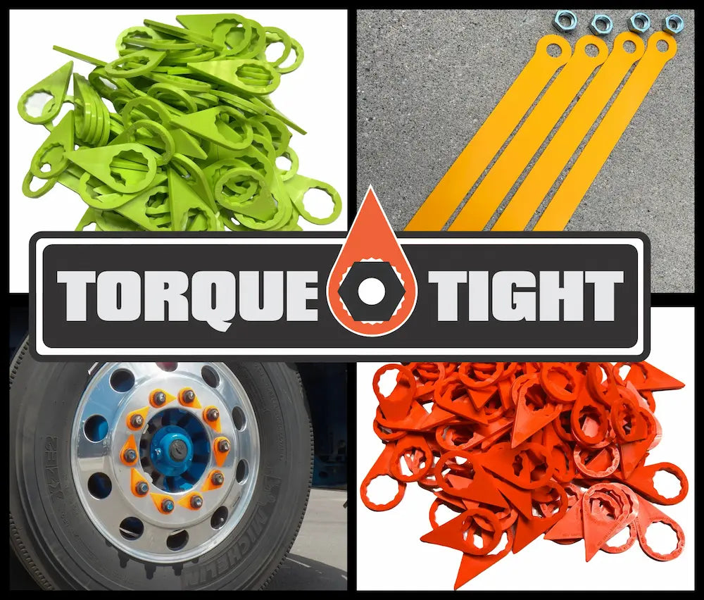
This is exactly the gap that Torque-Tight lug nut indicators are designed to fill. The operating principle is straightforward: a pointed polypropylene indicator is installed over each lug nut, with all indicators aligned to a common visual pattern when the fasteners are correctly torqued. If a fastener loses sufficient preload and begins to rotate under the Junker mechanism or thermal cycling, the indicator rotates with it, creating a visible misalignment that any driver can identify during a standard walk-around inspection -- before the fastener reaches a critical looseness threshold.
This transforms the pre-trip inspection from a visual check of bare lug nuts (which show nothing about torque state) into a rotation-detection scan that requires no tools, no additional time beyond a standard inspection, and no specialized training. A driver who spends 90 seconds scanning wheel positions before departure is performing a continuous monitoring function that no scheduled maintenance interval can replicate on a per-trip basis.
Torque-Tight indicators are available in sizes covering the full range of commercial vehicle lug nut specifications: 13/16", 21mm, 22mm, 27mm, 32mm, 33mm, and 38mm, manufactured by injection molding in the United States. For fleets with chrome-finish aluminum wheels, a chrome-plated indicator variant is also available for aesthetic compatibility without sacrificing detection function.
Critically, indicator performance over time depends on the durability of the indicator material itself. In outdoor fleet service, ultraviolet exposure degrades many plastic materials, causing color fading that reduces the visual contrast needed to detect rotation. Accelerated UV exposure testing per ASTM G154-23 Cycle 1 at 500 hours under ISO 17025-accredited laboratory conditions (Element Materials Technology, Report EWA176974) demonstrated that Torque-Tight indicators maintain color stability and visual contrast through extended service life -- a performance characteristic that lower-grade competitive indicator materials do not consistently achieve. Color integrity is not a cosmetic specification; it is a functional requirement for the detection system to work reliably across seasons and years of service.
Within a complete wheel safety protocol, Torque-Tight indicators occupy the continuous monitoring layer: always on, zero marginal time cost per inspection, requiring no torque tools. They complement, but do not replace, scheduled torque verification and mandatory re-torque after service. The three-layer protocol -- correct installation torque, re-torque at 50 to 100 miles, and continuous visual monitoring via indicators -- addresses each of the failure mechanisms described in this article at the point where it is most detectable and preventable.
Summary: A Systems View of Wheel Fastener Integrity
Wheel fastener loosening in commercial vehicle service is not a single-cause event. It is the compounded result of four interacting mechanisms: the inherent imprecision of torque as a preload proxy, thermal expansion mismatch that creates cyclic clamp force variation (documented at up to 42 percent loss in a single thermal cycle in real-world conditions), the Junker vibration mechanism that produces irreversible incremental rotation under transverse loading, and embedment relaxation that depletes initial preload in the first miles after service.
The CVSA data showing that wheel end violations account for nearly one in four CMV out-of-service findings is not a surprise given this physics. It reflects the reality that these mechanisms operate continuously and that inspection intervals, on their own, are insufficient to catch all degradation events before they reach a safety threshold.
The engineering response is a layered protocol: correct initial torque accounting for temperature conditions at installation, mandatory re-torque after the first 50 to 100 miles, and continuous visual monitoring at every pre-trip inspection. Torque-Tight lug nut indicators are the practical implementation of that third layer -- a low-cost, always-active detection method that puts rotation detection into the hands of the driver on every trip, not just on scheduled maintenance days.
References
- National Transportation Safety Board. (1992). Special Investigation Report: Medium and Heavy Truck Wheel Separations. NTSB/SIR-92/04. Washington, DC: NTSB.
- Junker, G.H. (1969). New criteria for self-loosening of fasteners under vibration. SAE Technical Paper 690055. Society of Automotive Engineers.
- Eccles, W., Sherrington, I., & Arnell, R.D. (2010). Describing loosening characteristics of prevailing torque nuts under transverse vibration. Proceedings of the Institution of Mechanical Engineers, Part C: Journal of Mechanical Engineering Science, 224(C12).
- Tennesey, W.W., P.Eng., & Reimer, L., B.Sc. (2006, June 8). Metallurgical Failure Investigation to Determine the Cause of Recent 'Wheel-Offs' Limited to Great Dane Trailers. File No. 06C-TL1760. Testlabs International Ltd., Winnipeg, MB. Prepared for Yanke Group of Companies.
- Element Materials Technology. (2024). UV Durability Test Report EWA176974. Conducted per ASTM G154-23 Cycle 1, 500 hours. ISO 17025 accredited laboratory.